Meditations on led badges

Table of Contents
Ok, so we’re working on https://cyberbadge.net and the project becomes more hard the more we’re trying to make it “production-ready”
After returning from 37C3 and talking with many smart and experienced people there, I decided to summarize everything there is, regarding the Cyberbadge project.
Cost estimation for cyberbadges⌗
Rev. 0⌗
This badge lived a good life.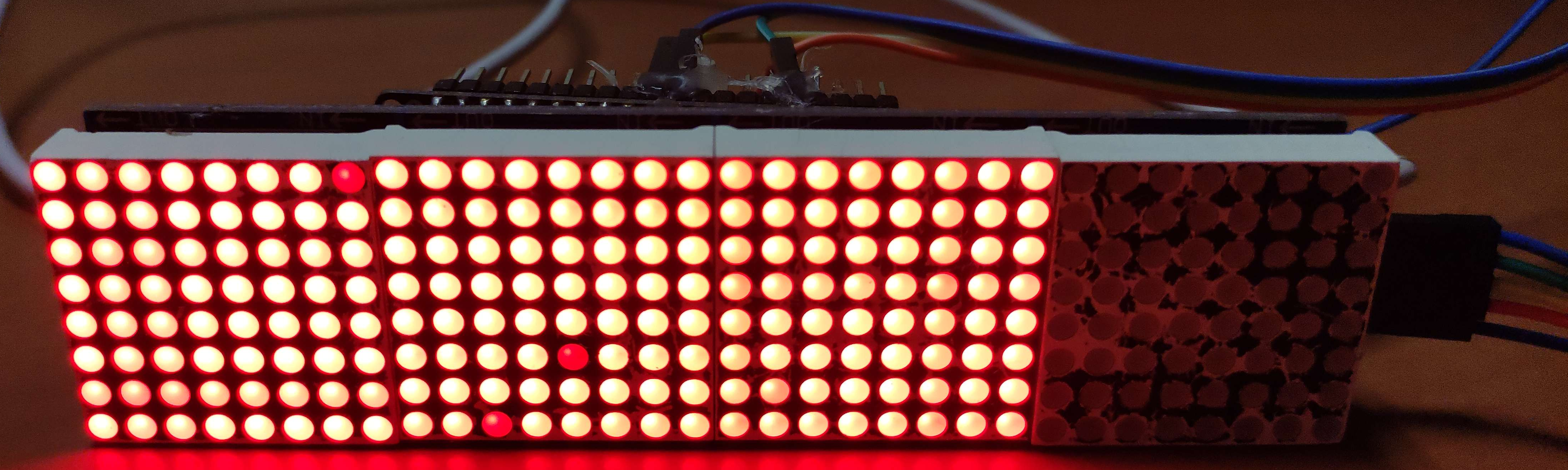
The “zero’th” revision of the cyberbadge was just a generic 8x32 red LED glued to an ESP32 and powered from a powerbank. There were never plans to commercialize this, but just for the reference, I’ll leave some summary
| Component(s) | Price per unit | link |
|---|---|---|
| LED matrix | $5 | https://elektroweb.pl/wyswietlacze/479-matryca-wyswietlacz-led-8x21-256-diody-sterownik-max7219-i-przewody-matrix-5904162803361.html |
| ESP32 module | $3 | n/a |
| Hotglue, wires, etc. | $0.5 | n/a |
| powerbank | 5$? | n/a |
Rev. 0.9?⌗
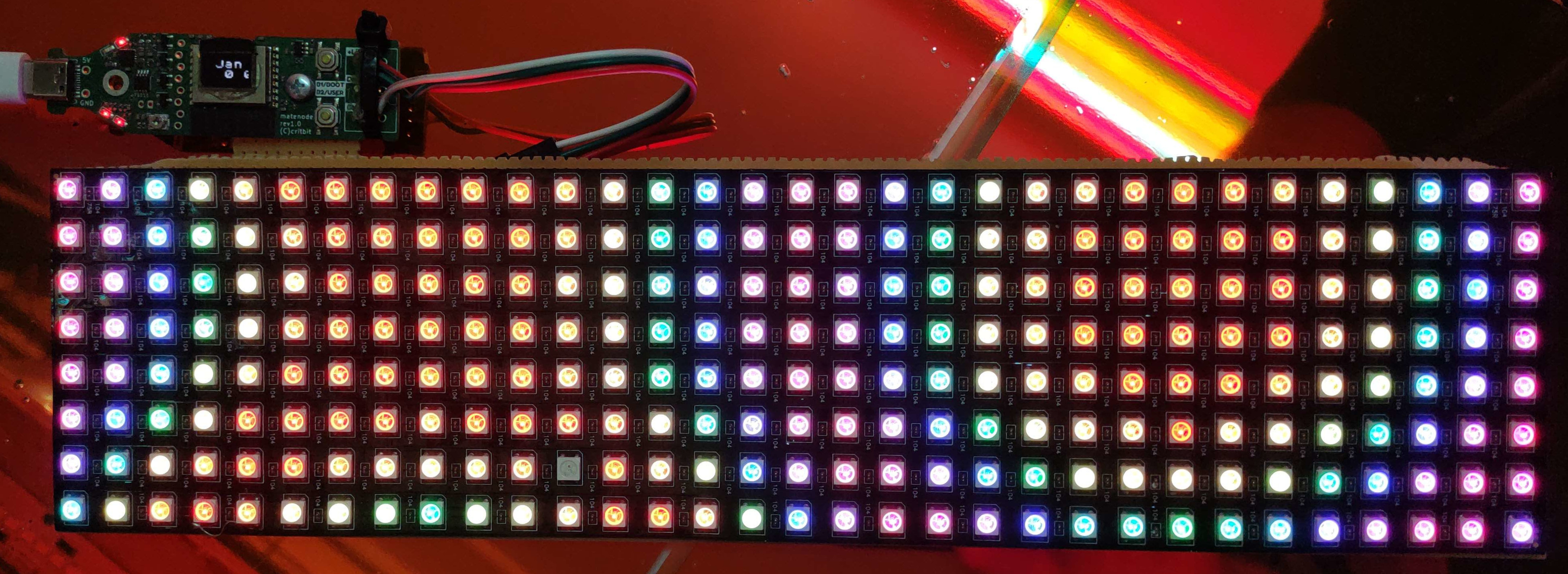
The prototype for the actual device was made from a Matenode and a generic WS2812 matrix from aliexpress
worth noting, we have virtually unlimited supply of free LiPo batteries from used one-time-use vapes. The problem is, we can’t really choose their form factor nor capacity, and they have to be dissasembled and prepared for their use manually.
| Component(s) | Price per unit | link |
|---|---|---|
| Matenode | $10 | n/a |
| ESP32 module | $10 | https://pl.aliexpress.com/item/1005001265647648.html |
| Lipo battery | free | n/a |
The costs are already kinda skyrocketing - it gets worse though.
Rev. 1.0 / 1.1⌗
![]()
This time we’re using WS2812-2020 LEDs on one custom PCB - the device starts too look profesional, but the costs rise again.
CB1.0 costed 450usd for 20PCS - 22.5usd per devices. ESP32 has to be sourced and soldered-in independently.
CB1.1 costs 750USD for 30PCS - meaning 25usd per device. Also, 5/30 devices arrive with one of the LEDs broken - meaning further costs of not-an-easy job of replacing the faulty LED.
On CB1.0 we used the batteries from used vapes - only 200mA batteries fit sensibly in the 3D printed case - these were to small, and the battery life was anything between 30min-2h.
For the CB1.1 we decided to buy better LiPo batteries (TODO - find their actual cost) for about $5.
The operation of preparing the badges for a client took one evening of ca. 5 people.
Let’s summarize the costs for the CB1.1
| Component(s) | Price per unit | link |
|---|---|---|
| Mainboard | $25 ($13 LEDs) | n/a |
| 3D printed case | (TODO estimate) | n/a |
| Lipo battery | free / $5 | n/a |
| Labour cost | (TODO estimate) | n/a |
I estimate the real cost is somewhere in the range of $40 per working unit.
Rev. 2.0⌗
This is the current iteration I’m working on. For CB1.1, out of $750 total cost, $400 was just WS2812 LEDs (256 per PCB) which is simply too much - we need to move to some dumb LEDs.
Since we’re manufacturing at JLCPCB, which is most likely the most cost-effective solution for our scale, the LEDs need to be choosen from their assortiment.
I decided on This LED which is the cheapest LED that doesn’t require their more expensive “advanced assembly” option ($8 vs $32 setup fee).
The routing of this board was a literal nightmare, but as it’s my hobby, and it’s kind of sudoku/meditation for me. it probably doesn’t make sense to estimate cost per working hour for this. See Schematic
In this revision, I decided to include an STM32 to handle multiplexing the LED matrix. I’m not sure it’ll stick. The idea was to have independent board for the LED matrix and the bluetooth MCU - which would kinda both increase and decrease the cost - 2 double-layer PCBs might be cheaper than one 4 Layer, requiring 2-side assembly.
For now the idea is to adjust the schematic to be compatible with a HUB75 - so that I can use already written libraries for ESP32 that can draw utilizing DMA transfer. Then the STM32 becomes obsolete.
Let’s move to the cost estimation - the board costed $55 for 5 pieces - but there’s no ESP32 yet there, only STM32 (for ~$0.7)
256 LEDs costed just $2 per PCB, but now some current drivers are required, though their cost is not very big too.
This is the driver I choose - since we have 32 rows of 3 colors - 96 lines need to be handled - this requires 6 drivers per PCB, but since they’re so cheap, this amounts to just $0.4 per PCB.
| Component(s) | Price per unit | link |
|---|---|---|
| LED board | $11 ($2.4 LEDs) | n/a |
| Lipo battery | free / $5 | n/a |
| ESP32 | ~$3 | n/a |
| Lipo charger, USB-C, other components | ~$3? | n/a |
| 3D printed case | (TODO estimate) | n/a |
| Labour cost | (TODO estimate) | n/a |
In summary, we get $12-$18 per piece, which amounts to $36-$100+ selling price, which becomes a bit too much if we’re targeting larger audiences. The queston is - how much can we further optimize this to drive the price lower?
- LED prices cannot be really be driven much lower
- The PCB is already 2-layer, and one-side assembly, but the order was only for 5PCs, so ordering larger batches should drive the price lower.
- ESP32 can be switched to ESP32-C3, saving $1-$1.5 per piece, but this might introduce problems that will be mentioned later.
- If the current draw is optimised really well, we can go back to using LiPos from used vapes.
- Some handy schematic tricks and well-written firmware may allow using cheaper charging IC and replacing the power switch with a button. Also maybe finding a chaper USB-C connector that handles CC-lines correctly and still doesn’t break down when you look at it more menacingly.
The grand aliexpress LED badge⌗
The most widely used badge on 37C3 was probably the one mentioned on top of the article.
FOSSASIA became quite famous in the hacker culture for creating their own FOSS app, that communicates with the device. They’re not touching the hardware nor firmware in any way though.
The guys mentioned that it would be really beneficial to be able to replace the stock firmware with their own - this would allow adding more fancy feature, while relying on big manufacturer’s production line, keeping the costs low.
Let’s have a look to see if it’s a feasible approach.
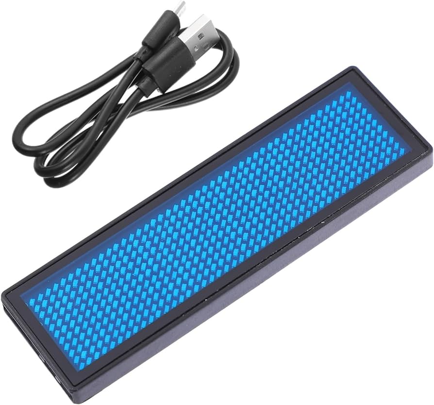
They claim full day of battery use (300mAh battery), which was confirmed by the members of FOSSASIA - cyberbadge currently cannot get even close.
The hardware⌗
LED matrix on top (I need a better camera):
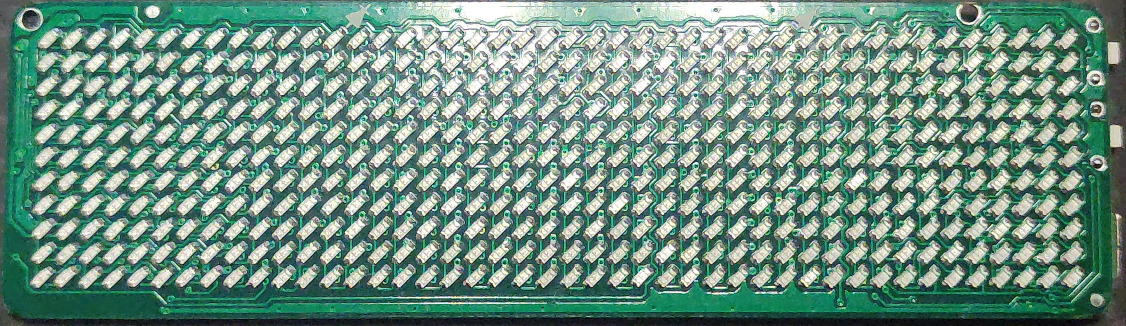 LED matrix on bot (glue residue from unsoldered LiPo, sorry!):
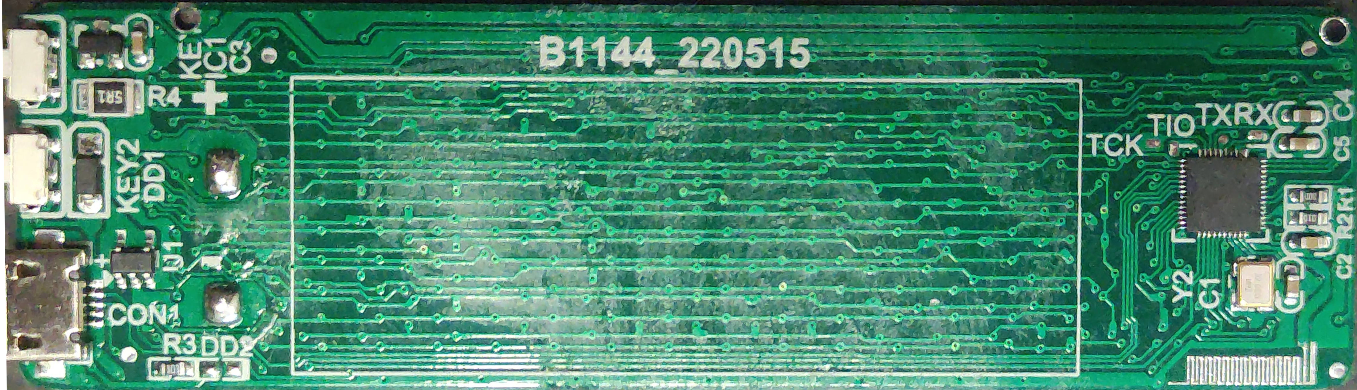
(at some point I’ll do the double layer reverse-engineering, but now just photos)
On the left side, we see the awful micro-usb connector and (probably) a LiPo charger IC. The side buttons are kinda hard-to-click, but they do their job.
On the right there’s the Bluetooth IC - CH582M. The crystal is required for proper 2.4GHz communication.
For the PCB designers - look, this board has literally no ground plane nowhere on this PCB - it has just 2 layers. The trace for wireless communication kinda just goes there. I have no idea where the ground return is.
Also, the shape shape of the 2.4GHz antenna is rather unique - though it was copied from an eval module of CH582M, which is good. On the other hand, it has been covered with tin (due to HASL process), and the tin sometimes randomly short the squiggly traces. The impedance control is a lie and this board confirms it.
(no it’s not, but it shows how much we can get away with if we don’t care about the range and actual EMC compliance probably)
The chip⌗
CH582 is actually not that obscure IC that I thought initially - it comes from the same company that makes CH340 USB-UART bridge we all love.
This chip costs around $1, and has a quite nice feature set:
- 512K flash
- 32K RAM
- Bluetooth 5.0 with support for 2M and LE-coded extensions
- Full speed USB 2.0
- Works from 2.3V, supports low power operation
- Every other basic peripheral you’d expect on an MCU
The problem is - this doesn’t seem like an IC dedicated for westerners - the manufacturer page is in chineese, the datasheet is available in english though.
SDK for CH58x⌗
They can be either programmed by USB or a dedicated programmer. I also think I’ve seen some instructions on how to use ST-link, but can’t find it now.
The page about flashing process (google translated) - https://www-cnblogs-com.translate.goog/iot-fan/p/13498088.html?_x_tr_sl=ru&_x_tr_tl=en&_x_tr_hl=en&_x_tr_pto=wapp
The programming tools have been involountarly open-sourced
- USB - ISP: https://github.com/ch32-rs/wchisp/tree/4b4787243ef9bc87cbbb0d95c7482b4f7c9838f1
- WLINK: https://github.com/ch32-rs/wlink
The SDK has also been ported to be compatible with Arduino - which is a good starting point, but as of january 2024 only basic peripherals were implemented.
The SDK itself can be accesed here https://github.com/openwch/ch583 - but it lacks a proper documentation, and some stuff is simply missing.
I’ll expand this section later
Custom FW for aliexpress badge?⌗
I did some basic checks - the device, when connected via USB, appears as a HID device - there exists a python script that allows setting your own text. For now, I haven’t found if the USB-ISP on these devices is locked by manufacturer.
Same as above, more research needed
How does the LED matrix work here⌗
As we have a look at the bottom part of the board, no driver for the LEDs can be seen - this most likely means the LEDs are charlieplexed.
The badges come in various resolutions - let’s assume we have 12x48 - 576 LEDs - meaning we need just 25 pins to control everything.
Charliepexing comes with a cost though - the duty cycle becomes lower than in cyberbadge 2.0 case. I’m not sure how low though, need to dig into this algorithm deeper.
References:
- [1] https://www.instructables.com/Charlieplexing-Made-Easy-and-What-It-Even-Means/
- [2] https://en.wikipedia.org/wiki/Charlieplexing
The current draw and where does it come from⌗
I’ve been told that the aliexpress badge can achieve these long work hours, because of the way they handle bluetooth communication.
The badge activates bluetooth only for the short time, after a button has been clicked. In this short time, user can upload a new content for the screen. After uploading (or a short timeout) the bluetooth becomes inactive again.
This stands in contrast to the cyberbadge, where the connection is kept alive, and user can update the content of the badge at all times, even draw pixels interactively.
L in BLE stands for low power???⌗
My first reaction to this “energy-saving” theory was - it’s bullshit. I’ve designed BLE devices in the past, and they can be extremely power - efficient. The protocol was designed around that.
Even though transmitting and receiving BLE data can draw tens of milliamps, the TX/RX windows are very short, and the burden of the (paradoxically) more power-hungry process, which is receiving BLE packets for pairing, is on the host device. After connection is estabilished, the TX/RX windows are negotiated very accurately, meaning that no current on the low-power device is wasted.
We can use a power profiler for nRF5x series, provided by nordic semiconductor to do some rough estimation on how current consumption would look like, in case there’s constant transmission between smartphone and a BLE badge.
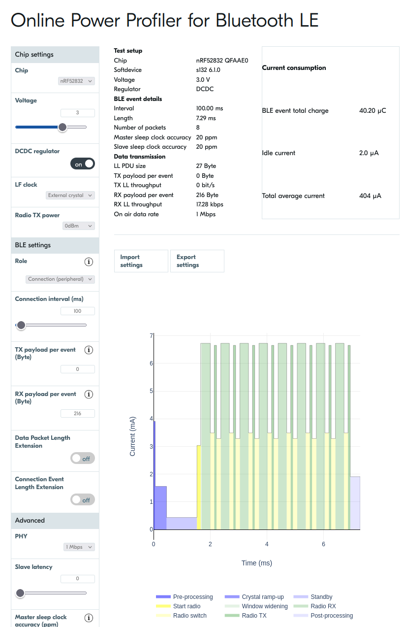
As we see, the average current lies below 1mA, which matches my expectations better. But then I realized.
L stands for Looser if you’re poor⌗
Nordic semiconductor spent multitude of money on getting where they are - leading in the area of ultra-low-power bluetooth devices. It’s no accident apple tags use nRF52 inside - they can work up to 1 year on CR2032 battery.
I actually implemented a device with simillar battery life, running on CR2032 - it could broadcast live temperature/humidity data for 1 year straight, every 1.5sec, utilizing advertisement packets. This is why I have some knowledge of how this internally works.
In this chapter I’ll try to share my knowledge about it, and will try to find out why do other MCUs can’t handle bluetooth that well.
nRF5x⌗
nRF5x (nRF51, nRF52 and the new nRF53) chips have completely different software architecture from ESP32 family. They’re extremely optimized for power efficiency, and most of the time, the chip is asleep, waiting for an event to handle. Also, they can’t do WiFi.
Bluetooth protocol requires very strict timing constrains - the connection must be kept alive, and the transmission windows are very narrow. In case of nRF52, the user doesn’t even have access to these timing functions - everything is handled by a “softdevice”, which is a properietary blob that manages everthing that’s happening on a MCU.
The way I understand that, this is very similar to how linux kernel works - everything is event-driven, there’s no “main loop” accesible to the programmer. This guarantees, that every time constrain required by the bluetooth protocol is handled properly, and the MCU is awake only, when there’s something to do - in other cases, it sleeps.
Actually, achieving this ultra power effecient operation is not really hard for the developer - you just have to make sure there’s no unnessesary current leakage on the device, and make sure any operation that interfaces with any external devices, does this as fast as possible, so that the core can go right back to sleep.
ESP32⌗
So, now we enter ESP32 realm - here, the whole device runs on freeRTOS. This serves a similar purpose to the “softdevice” - allowing every subroutine to be executed within a specific time constrain, but the control over the timings cannot be as perfect as in nRF devices.
FreeRTOS is based around “ticks” - every N miliseconds, an timer interrupt jumps the code into the freeRTOS slicing subroutine, which decides, what task does require processing power right now. From my experience, N usually is set to 1ms, but in case of ESP32 it seems 10ms value is used sometimes.
The problem is, sleeping and waking up ESP32 is not cost-free - there’s a power cost for this operation. The result is, that waking up and sleeping every tick is simply not worth it, in terms of power saving. The way power-saving on ESP32 works, is that you enable “tickless idle” mode - this makes the ESP32 enter light sleep after N (usually 3) ticks of freeRTOS, no task has been run, so ESP can go to sleep.
Bluetooth has configurable “connection interval” - the time period between a “keepalive” packet is sent, and also any data that needs to be transmitted. Value of 100ms tend to be used.
Now the problem becomes obvious - because the device is not designed for fast wakeup - keeping alive the bluetooth connection requires it to run the MCU for a long time, doing basically nothing, and wasting the power (the core requires tens of miliamps to run).
Also, there’s other issue - on cyberbadge 2.0, the matrix is “dumb” - meaning that it has to be redrawn constantly. If the MCU could enter sleep mode fast - we could send a line of pixels, then sleep for some (miniscule) time, and then wake up to draw the next one. It’s probably not possible, even if we utilize DMA somehow, but I need to confirm it still. TODO read into this
There’s also one more power-saving trick available - ESP32s can have Ultra Low Power Coprocessors. This might be fast enough to bitbang the screen, but more research is needed TODO research
CH58x⌗
Now we enter speculation area, because I’m not familiar with CH582 SDK - my theory is that software architecture stands somewhere between nRF52 and ESP32 - there’s no freeRTOS so the timings can be controlled very strictly, but still there’s no hyper-optimisation seen on nRF52 - handling bluetooth requires the programmer to periodically interrupt the execution of the main draw/sleep loop.
This might mean that ommiting handling the bluetooth connection allows the CPU to run only during the render/charlieplexing phase, possibly also at lower clock.
I even have an idea how to test my theory - exact current draw graph correlated with monitoring a single pixel via oscilloscope probe would maybe confirm if I’m right. TODO test
Core voltages⌗
Both nRF5x and CH58x contain an quite advanced power managmenet units - these are integrated DCDC converters and ULP LDOs, generating low voltages for the cores. I can’t find what voltage does CH582 use, but in case of nRF52 it’s 1.3V.
In case of ESP32, I’m not sure what the voltage of the core is, but for sure there’s no such advanced PMU that would help conserve the energy. Rather, their idea of low-power operation is to utilize the low-power coprocessors, and then wake up the MCU when there’s a task to be done.
TODO check if alibadge uses LDO or direct LiPo voltage
Let’s do some math⌗
The documentation for the aliexpress badge says it can work anything between 8-16h. Let’s assume 12h for now.
The battery in my unit had 320 mAh. There’s no step-down circuit for the LEDs (the built-in DCDC can power only the core, not IOs).
320mAh / 12h means 27mA average current.
Now we move to the cyberbadge or we will, I need to measure this stuff still
Conclusions⌗
This article is Work-in-progress, now I need to perform some current measurements for the revisions.
Still I’ll start collecting some conclusions I already have
Should we just move to another MCU for CB2.0?⌗
Using nRF52 would probably solve the issue with battery life. But I really don’t want to make that move, due to many reasons:
- nRF52 SDK is relatively good, but requires some time getting into it. In theory there’s some arduino framework support though.
- For ESP32 we have WLED firmware - this grants us a lot of useful features OOTB. The ideal course of action would be implementing bluetooth API for WLED
Bluetooth on WLED⌗
The maintainers do not agree on adding bluetooth functionality currently - for the simple reason this functionality would not be able to run on ESP8266 (no bluetooth) and low-end ESPs (the firmware wouldn’t fit on 4M flash after adding bluetooth)
https://github.com/Aircoookie/WLED/issues/1382
Still, a PoC have been already implemented (though it seems abandoned for now) - ideally I’d finish implementing this, making it either an usermod or variant compilation for compatible ESPs.
https://github.com/Aircoookie/WLED/pull/2925
Using WLED as the main firmware would largely benefit the project, as we’d also add live-drawing interface over the course of development, maybe also improve image/animation save/upload feature. Maybe we could also get more manpower from people interesting in these features.
Next steps⌗
The measurements of the actual current draw need to be made:
- Plotting the aliexpress badge’s current over time, either with BLE on or off
- Messing with CB1.1 - trying tickless idle (this can work because WS2812 displaying static text does not need updating)
- CB2.0 - asserting required refresh rate